Bibliotheca Hertziana, Max Planck Institute for Art History
|
|
| Elisabeth Kieven, Hermann Schlimme †, Günter Eger |
The Sources
Roma, Accademia di San Luca, ASL 0140 |
|
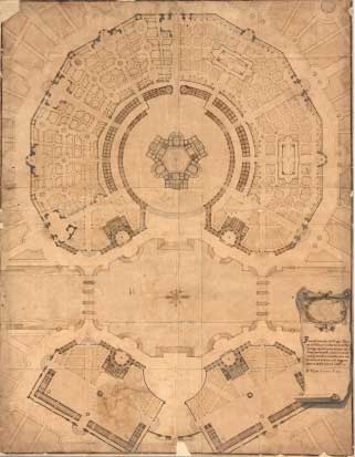 |
This is the plan of the overall layout. It shows all the buildings sectioned. The garden layout is divided into a left half and a right half and shows two different possible versions of the layout. An abstracted plan of the storeys. Its clarity facilitates our understanding of the inner structure of the building. It was not intended to be seen in detail. The intention was that it should still be comprehensible when viewed in a presentation to a larger public at a distance of several metres. Property of: Accademia di San Luca in Rome, Italy More information about the plan and its high resolution scan is available online in our Lineamenta Database. Please click here. |
Roma, Accademia di San Luca, ASL 0141 |
|
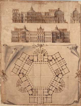 |
The plan shows the central palace of the layout. Above is a section through the building; below, an elevation. The third zone of the sheet consists of the ground plan, which is divided so that the left half shows the first upper floor (Piano nobile)and the right half the ground floor (Piano terra). The plan clarifies the variety of room relations to each other and the wealth of the architectural articulation of the design. Each stair, column, window and door is represented; even the shape of the individual ceiling vaults is established here. Property of: Accademia di San Luca in Rome, Italy More information about the plan and its high resolution scan is available online in our Lineamenta Database. Please click here. |
Roma, Accademia di San Luca, ASL 0142 |
|
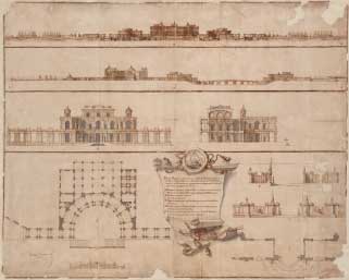 |
Both the upper zones of the plan show sections through the overall layout. The orientations of the sections are turned towards each other by 90 degrees. The third zone shows the elevation and section of one of the four water pavilions (overlooking the lake). The lower fourth zone shows the ground plan of the ground floor of the water pavilion to the left and a series of detail plans of a garden entrance to the right. In the centre is a fictive plaque with an inscription, with explanations of the project. Property of: Accademia di San Luca in Rome, Italy More information about the plan and its high resolution scan is available online in our Lineamenta Database. Please click here. |
Berlin, Kunstbibliothek, HdZ 1151 |
|
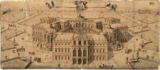 |
The well known bird's eye view of the project. Property of: Kunstbibliothek in Berlin, Germany More information about the plan and its high resolution scan is available online in our Lineamenta Database. Please click here. |
Comparising the two plans of the palace
ASL140 |
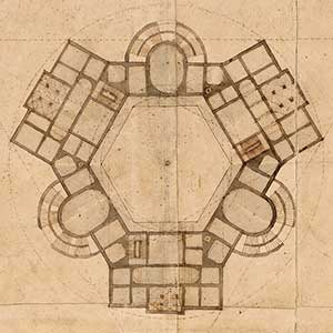 |
The plan of the whole site shows an abstracted plan of the storeys of the palace. Its clarity facilitates our understanding of the inner structure of the building. It was not intended to be seen in detail. The intention was that it should still be comprehensible when viewed in a presentation to a larger public at a distance of several metres. |
ASL141 |
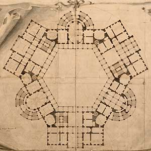 |
This plan clarifies the variety of room relations to each other and the wealth of the architectural articulation of the design. Each stair, column, window and door is represented; even the shape of the individual ceiling vaults is established here. The left side shows the first upper floor (Piano Nobile) The right side shows the ground floor (Piano Terra) |
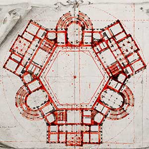 |
Here you see an overlay of both plans on the same scale: ASL140 in red, ASL141 in black. As can be seen, at no point do both plans exactly coincide! |
I therefore decided to deduce the basic design principles from both plans and to examine them side-by-side. Questions of detail, however, will only be clarified with ASL141, since this plan is more accurate and shows more detail. ASL140 on the other hand more clearly shows the geometric basic idea of the plan.
|
The lack of coincidence between the two plans means that the palace model cannot be exactly superimposed over the larger plan. This “error” can in fact be perceived also in the CAD model, where the palace model, modeled from the plan ASL141, stands on the ground, which shows the plan ASL140. The picture on the left shows this in detail. |
Comparising the plans and the bird's eye view
I would like to go into a little more detail in discussing the differences between the orthogonal plan drawings and the bird’s eye view.ASL140 |
|
These differences are undoubtedly clearest in the different representation of the park layout. All the surrounding buildings are lacking in the bird’s eye view. The representation of the immediate surroundings is limited to a simple green area, traversed by concentrically laid-out paths. In the distance a wall, emphasized by small angular buildings at its corners, surrounds the layout. So the bird’s eye view concentrates almost entirely on the main building; the observer has an unrestricted view of it and can admire its finely layered geometry. The oval domed pavilions, with their two-storied saloons, projecting to the sides of the main facade, have a powerful and dominating effect in the bird’s eye view. In the orthogonal view they are more harmoniously and discreetly bound into the total form of the palace. The reason for this could be the fact that the trapezoidal buildings, which the oval pavilions intersect, are drawn narrower in the bird’s eye view than they are in the orthogonal plans. As a result the oval pavilions are only half-incorporated in the building block. The lateral oval pavilions wholly intersect the flat roofs right through to the inner courtyard. By this alteration they are given greater autonomy. The oval domed banquet hall placed in the centre in the drawing is however again subordinated to the inner courtyard. Here the coherence of the inner courtyard is what is most important for the drawing, since otherwise the ensemble effect of the palace building as a whole would be lost. Lastly, a different scale and an altered façade system are adopted for the oval pavilions in the bird’s eye view: instead of drawing two windows, the one above the other, as in the elevations, Juvarra draws more monumental two-storied arched windows. The oval pavilion to the right, moreover, is given added emphasis through the ingenious deployment of shaded areas. The rounding of the oval is rendered in all shades of grey down to pure black; the deep window jambs are emphasized by bright highlights and the exterior flight of steps stands out brightly against the grey shaded background. The light works here like the lighting of stage sets in a theatre. But Juvarra used even further visual tricks in the bird’s eye view, in order to make his design convincing to the observer. The roof expanse has a very soothing effect thanks to its large and smooth interconnecting flat planes. In its rigour, it forms a clean upper termination especially to the inner courtyard. The central axes of the building complex are alone given added vertical emphasis by superstructures rising above the flat roofs. So as not to disturb this fragile composition, Juvarra, apparently deliberately, decided not to roof over the upward-ascending spiral staircases, although these represent the only access to the roof; their inconspicuous unroofed apertures can be seen to left and right on the flat roof of the frontal block. For reasons of symmetry a spiral staircase ascent is even drawn on each inner corner in the bird’s eye view, although this is quite at variance with the ground plan, which shows rectangular stairwells at every second corner. The huge width of the inner courtyard is suggested by Juvarra in the bird’s eye view by two ingeniously combined devices: first, he draws the palace altogether squatter than in the elevations, and, second, he represents the portico in the inner courtyard as only single-storied. This representation differs in this respect from all sections of the project. The richly decorated and differentiated structure of baroque architecture could not be represented in all its detail in a bird’s eye view. The perspective lines converging on the vanishing point on the horizon rapidly merge together to form an ugly black spot. So Juvarra was forced – despite the large size he had chosen for the sheet – to represent the façade elements in far more simplified form than in his elevations. The subtle balance between wall aperture and wall surface is altered in such a way that the building appears heavier and more monumental than in the orthogonal plans. Juvarra cleverly counteracted this effect by distributing lively and playful figural groups through the sheet: they are clearly shown too large in scale in relation to the building. But it is just this incongruity that gives the observer the wished-for impression of lightness and elegance in the building. |
ASL141 |
|
This plan clarifies the variety of room relations to each other and the wealth of the architectural articulation of the design. Each stair, column, window and door is represented; even the shape of the individual ceiling vaults is established here. The left side shows the first upper floor (Piano Nobile) The right side shows the ground floor (Piano Terra) |
|
Here you see an overlay of both plans on the same scale: ASL140 in red, ASL141 in black. As can be seen, at no point do both plans exactly coincide! |
I therefore decided to deduce the basic design principles from both plans and to examine them side-by-side. Questions of detail, however, will only be clarified with ASL141, since this plan is more accurate and shows more detail. ASL140 on the other hand more clearly shows the geometric basic idea of the plan.
|
The lack of coincidence between the two plans means that the palace model cannot be exactly superimposed over the larger plan. This “error” can in fact be perceived also in the CAD model, where the palace model, modeled from the plan ASL141, stands on the ground, which shows the plan ASL140. The picture on the left shows this in detail. |